Automatic plant watering device
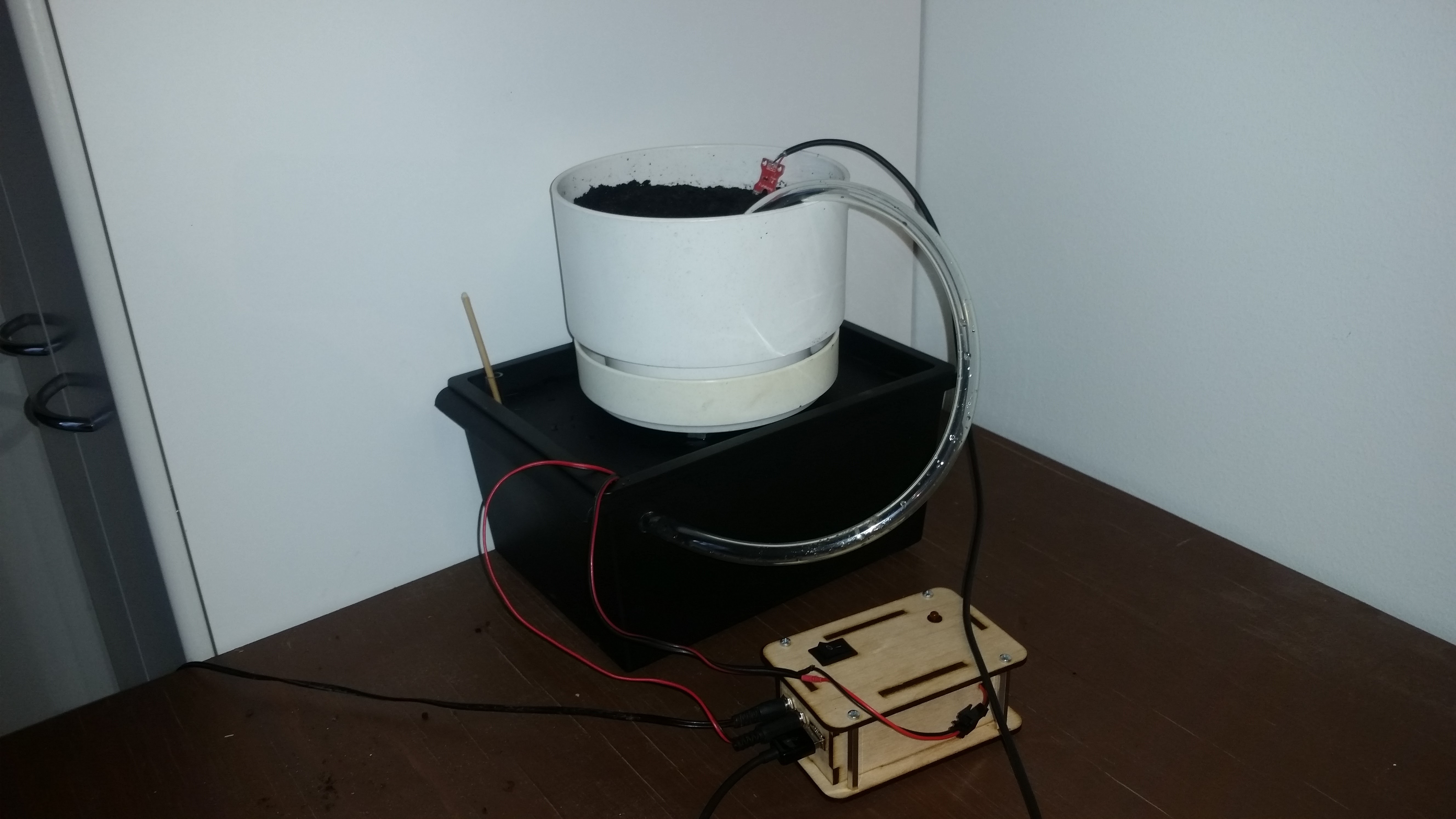 Call it a robotic gardener or an artificial green thumb, it is a device that keeps the soil of my chili plant wet.
The principle is simple. A moisture sensor hooked up to an ATtiny85 microcontroller measures the moisture of the soil every hour, and if the moisture is lower than a certain threshold, it turns on an aquarium pump to move some water from a tank into the pot. The tank has some holes on the lid and the pot sits on top of it, so that if the sensor malfunctions and too much water is pumped into the pot, it will just flow back into the tank. The tank can hold about 5 liters of water and, to prevent growth of algae, it is made of an opaque plastic.
The parts
- ATtiny85 microcontroller (or an Arduino)
- FunDuino soil moisture sensor
- Aquarium pump with a piece of fitting hose
- 12V power source (I use a power cord from an old external hard drive)
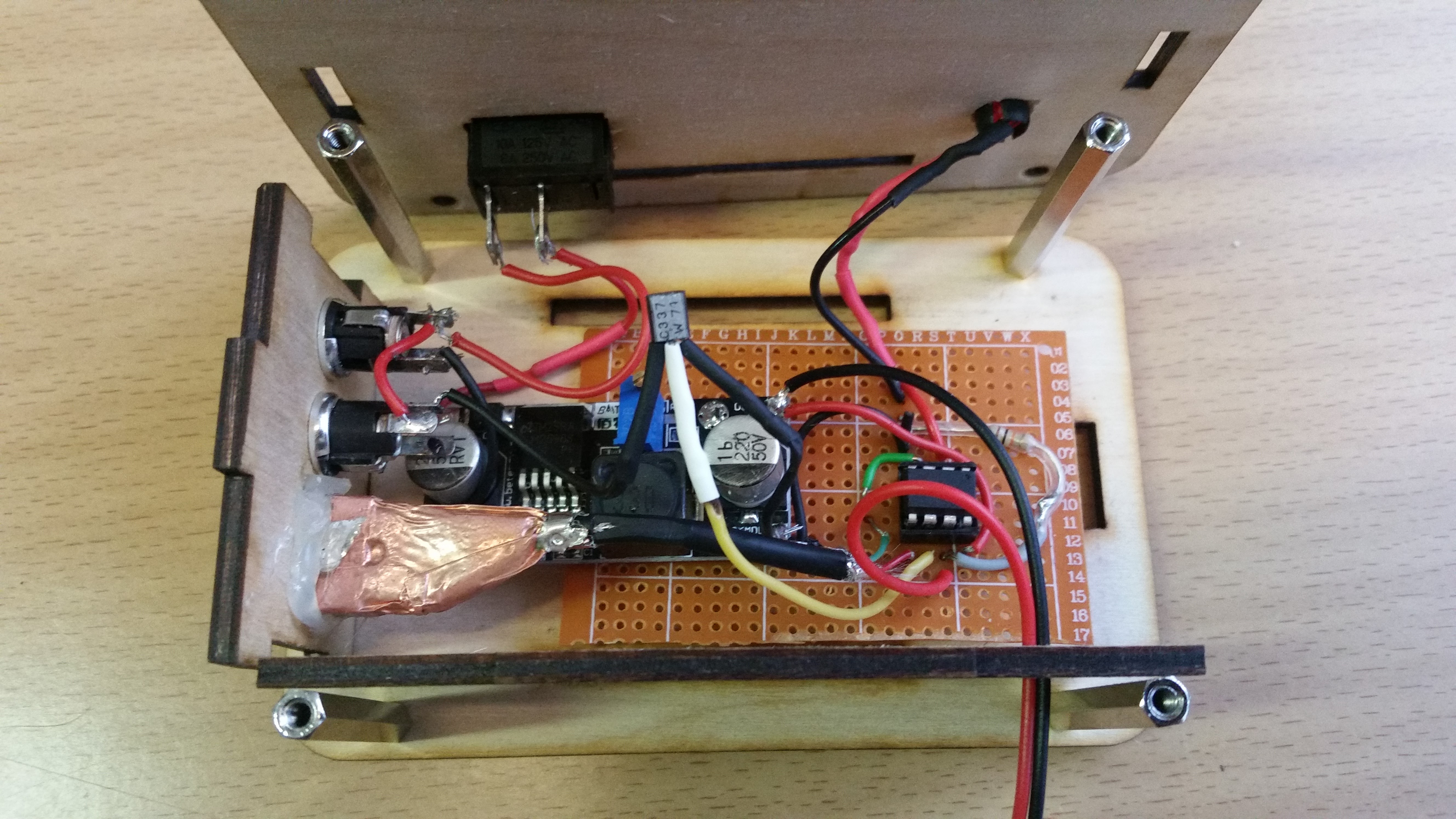
- 12V to 5V converter (I used an LM2596 buck converter, but an LM7805 regulator would probably have been a better choice since it is cheaper and smaller. Hence, the circuit diagram will show an LM7805 unit, but in the photos there will be an LM2596.)
- NPN Transistor (BC337 or similar)
- 10kOhm resistor (to make a water level sensor)
- LED and a current limiting resistor of suitable resistance (the LED will be blinking while the water level in the tank is low)
- Basic electronics equipment – Circuit board, wire, some solder…
- Everything you’d expect to need to grow a potted plant – A pot, some soil, a water tank…
- A box to hold the electronics (I made mine out of laser-cut plywood)
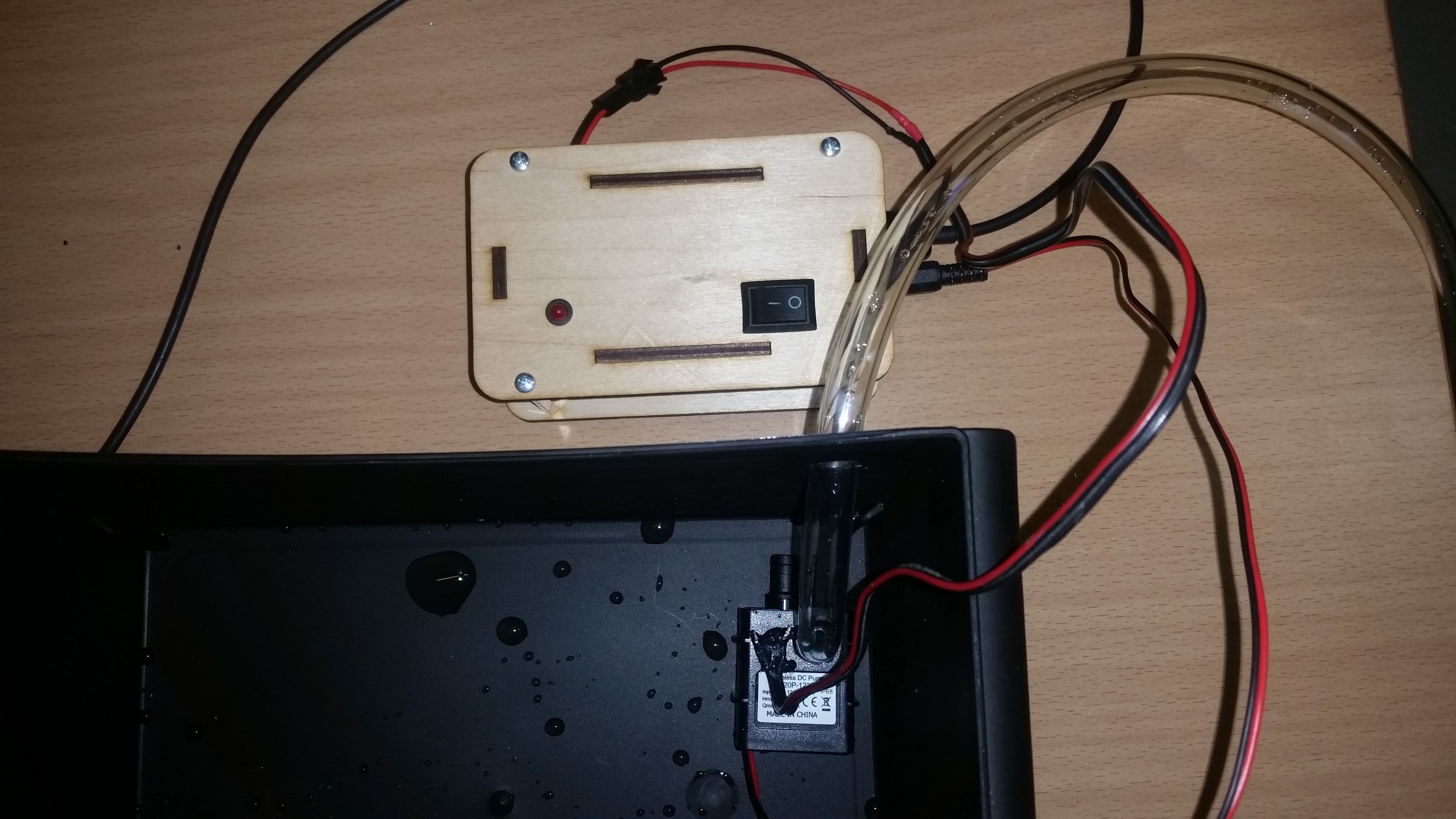
The electronics
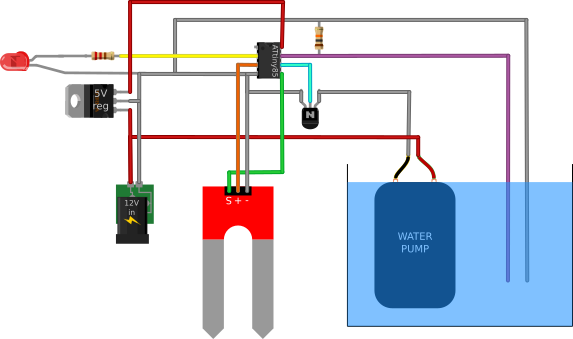
Note that the VCC pin of the soil moisture sensor is connected to an output pin of the microcontroller instead of being constantly powered with 5V. To prevent corrosion, the sensor should be powered only briefly while taking a measurement.
The two wires going into the water tank are a simple water level sensor. The stripped ends of the wires should be close to each other but not touching, so that the wires being underwater will result in a significant drop of resistance, which can be measured with an analog input pin of the microcontroller. Also, there should be a 10kOhm resistor between the wires above the water level.
The NPN transistor pins should be connected in the following way: Collector to the ground wire of the pump, base to an output pin on the microcontroller and emitter to the ground pin on the microcontroller. This way the pump (which operates on 12V) can be controlled with the microcontroller.
 The code
At start, the LED is flashed a couple of times to indicate that the device has turned on. Then, the current moisture of the soil is measured and stored in the suitableMoisture variable. Each hour, the moisture is measured again, and if it is below the suitableMoisture threshold, the pump will be briefly turned on to water the soil. Thus, the moisture level should theoretically never drop below what it was when the device was last turned on. To change the desirable moisture level, the user can simply turn off the device until the moisture is at the new desirable level. No reprogramming required.
#define led A3
#define moistureSensor A2
#define waterLevelSensor A1
#define pump 1
#define vout 0
#define wateringDuration 2000
#define delayBetweenWaterings 3600000 //3600000 ms = 1h
int moisture;
int suitableMoisture;

void setup() {
    pinMode(led, OUTPUT);
    pinMode(moistureSensor, INPUT);
    pinMode(waterLevelSensor, INPUT);
    pinMode(pump, OUTPUT);
    pinMode(vout, OUTPUT);
    digitalWrite(led, LOW);
    digitalWrite(pump, LOW);
    digitalWrite(vout, LOW);
    for(int i = 0; i < 4; i++)
    {
       digitalWrite(led, !digitalRead(led));
       delay(100);
    }
    suitableMoisture = getMoisture(moistureSensor, vout);
}
void loop() {
  moisture = getMoisture(moistureSensor, vout);
  if(waterInTank())
  {
      if(moisture < suitableMoisture)
      {
          water();
      }
      delay(delayBetweenWaterings);
  }

  else
  {
     while(true)
     {
        digitalWrite(led, HIGH);
        delay(500);
        digitalWrite(led, LOW);
        if(waterInTank())
            break;
        delay(500);
     }
   }
}

int getMoisture(int pin, int power)
{
   digitalWrite(power, HIGH);
   delay(20);
   int reading = analogRead(pin);
   delay(20);
   digitalWrite(power, LOW);
   return(reading);
}

void water()
{
   digitalWrite(pump, HIGH);
   delay(wateringDuration);
   digitalWrite(pump, LOW);
}

bool waterInTank()
{
   if(analogRead(waterLevelSensor) > 20)
       return(true);
   else
       return(false);
}



Hello
Thanks for sharing this project!
I have build this using an arduino ,(testing with uno will use nano later) and relay with optocoupler.
But in my case it works the other way around.
To get it working I had to chanche by waterlevel and moisture.
Can someone explain?
Hello
Can someone explain?
in my case it works the other way around.
resistor 10k false parallel
resistor 10k true in series
problema whith waterLevelSensor A1 it works the other way around.
if A1 water sensor is an input reading vol level, then the cable going to water should be +5v not Gnd no? if ground goes to water it would still read 0v.
To reply the above conecting in series or not putting the 10k at all should leave an open circuit that gets closed when water level is high. maybe there is some level difference between +0v GND and input pin? that still reads the closed circuit as an analog change.
let me know if it makes sense