ESP8266 troubleshooting
I had already 3 ESP8266-modules but I didn’t manage to get any of them to work.
I had connected also VCC (3,3 V) – CH_PD (CHIP_EN on ESP-201) together, but no success before.
Scenarios I faced (with ESP-201, ESP-03 and ESP-04 module):
- No response to “AT” message
- Response to “AT” was just one, two gibberish symbols like “€ü/” and so on…
- Response to “AT” was just the same “AT” (echo).
Success with ESP8266-01 module:
- I read and found out that is better to connect VCC – CH_PD with pull-up resistor. I used 3,3K Ohm one -> limits current to ~ 1 mA through VCC to CH_PD.
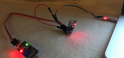
- Used CH340 USB-serial. Download driver from here for Win 7/Win 8 (32- and 64-bits).
- Also CP2101 works fine. Find Win7 / Win8 drivers here.
- Baudrate to 115200, CR+LF settings in terminal (Termite, ESplorer for example).
- One desktop computer could supply enough power also with CP2102 USB-adapter.
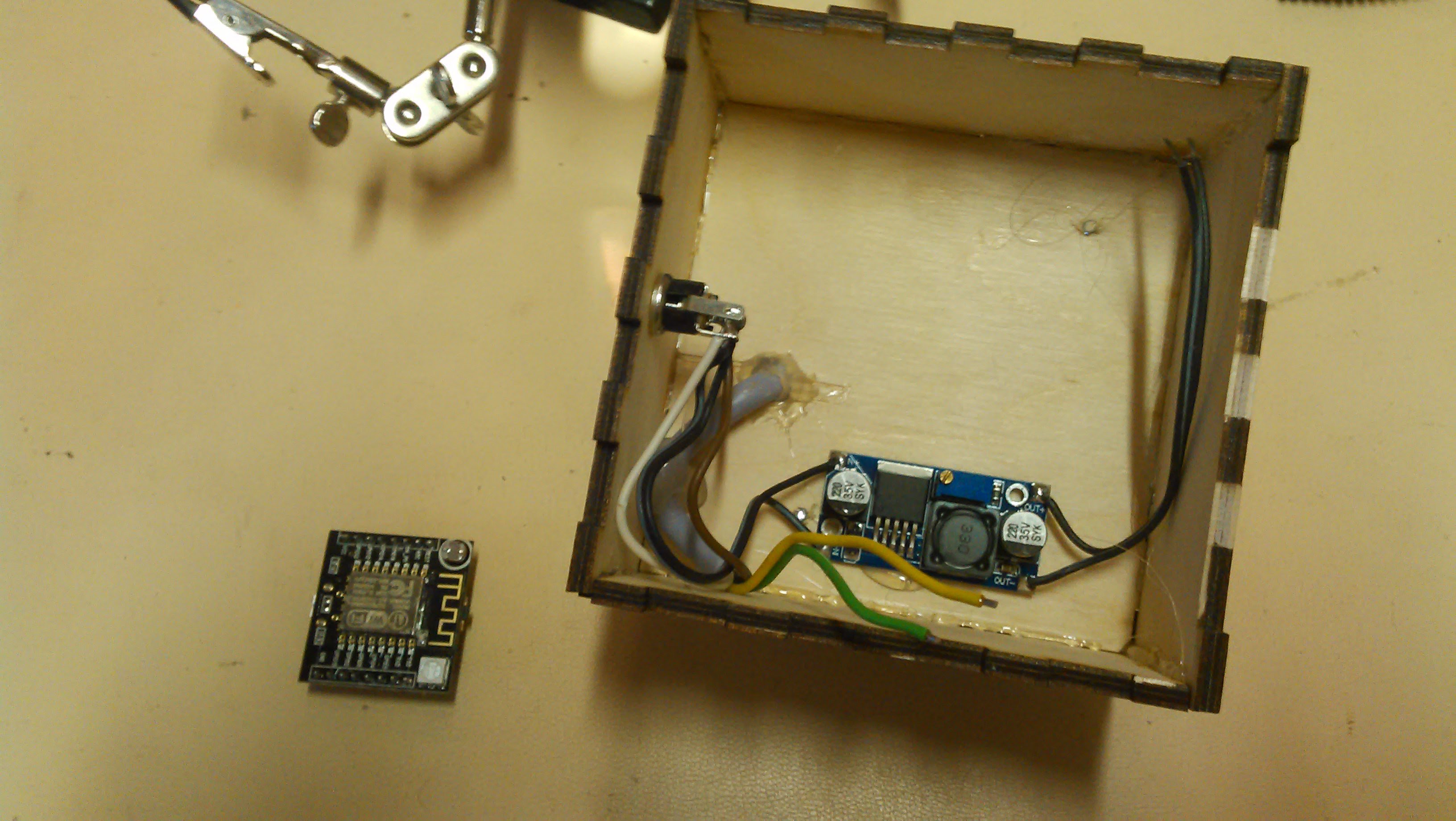
- Another desktop computer couldn’t. With that I used DC-DC module that outputs 3,3 V. Connected DC-DC converter’s: GND – GND (ESP8266), VCC – VCC (ESP8266) AND (this is important!) connect GND of USB-serial adapter with GND of ESP8266. Then there is all the same ground potential and it won’t cause interference with serial communication. So GND was in every (ESP8266, USB-serial and DC-DC module the same).
- This applies to every use case of USB-serial.
- Another desktop computer couldn’t. With that I used DC-DC module that outputs 3,3 V. Connected DC-DC converter’s: GND – GND (ESP8266), VCC – VCC (ESP8266) AND (this is important!) connect GND of USB-serial adapter with GND of ESP8266. Then there is all the same ground potential and it won’t cause interference with serial communication. So GND was in every (ESP8266, USB-serial and DC-DC module the same).
Success at last after failing with so called ESP-201 and ESP-03 module:
- I was mislead to look at the pin solders of the ESP-201 module after countless times of trying to get ESP-201 to work with same principle as I’ve got ESP-01 module without any proper result.
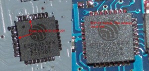
- So I started to look at the circuit board. ESP8266 chip had solder shorting some legs together. There was nothing wrong with that because in the ESP8266 schematic they should be connected together. ESP-01 does this on the PCB.
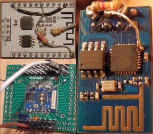
- Success at last:
- For virtually every other than ESP-01 module you need to connect GPIO15 pin to GND in order to boot form the flash memory of the device. So that comes in addition to ESP-01 module. I soldered these pins together. According to this source GPIO15 is not tied to the ground ONLY when ESP8266 firmware is booted from an SD-card. When soldering GPIO15 and GND you still are able to update the firmware when you connect GPIO0 to GND (Download code from UART).
- These connections can obviously be done first with dupont-jumper cords to ensure that everything is working. Then to save cords and space taken by the cords is wise to solder the mentioned pins together.
- Got ESP-201 module running and burned NodeMCU in already!
- This getting started documentation can be also applied to other than ESP-01 modules if read carefully through.

